
Search the wiki
Extracting a 32bit Displacement Map from ZBrush

Introduction
In this walkthrough, we’ll be using ZBrush to extract a 32bit displacement map and Maya/Arnold to test the map.
Assessing the Model
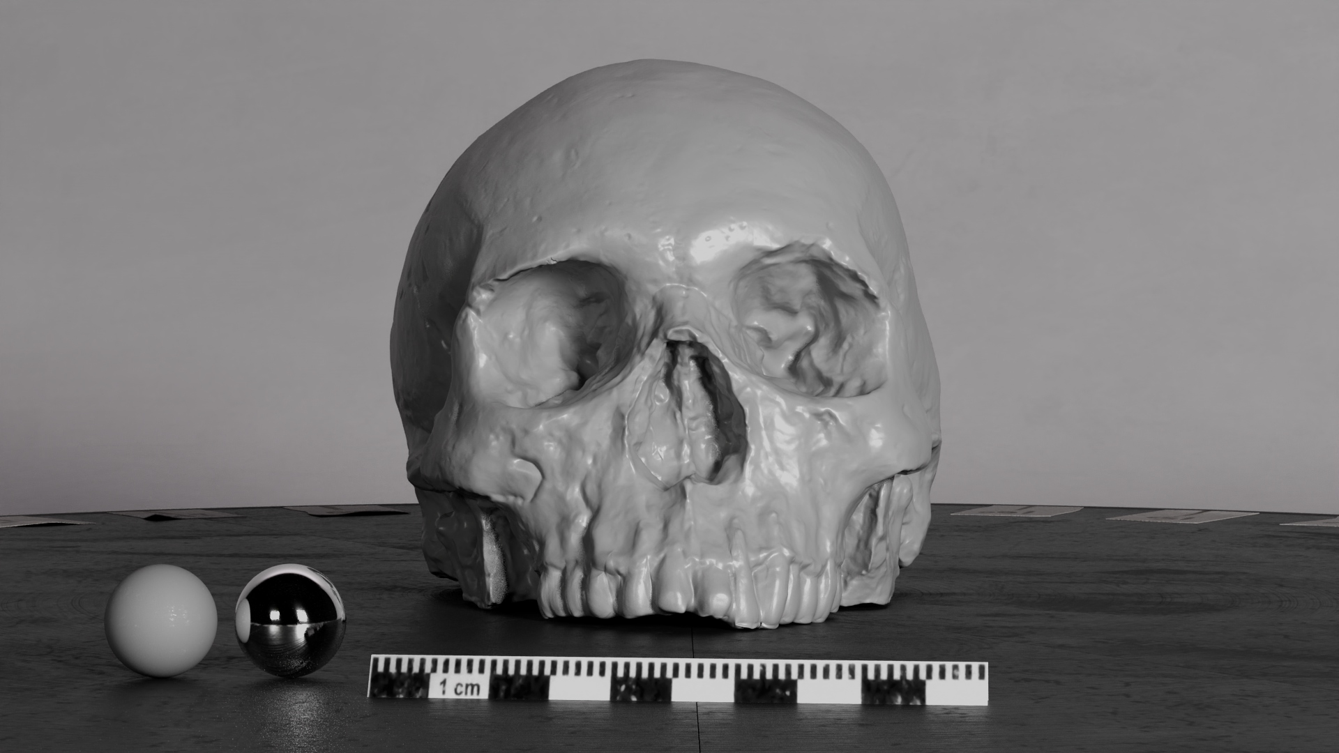
For this tutorial, I’ll be using a model of a skull with 2 UDIMs, as illustrated below. In Maya, I have the lowest resolution model (Lod1), which I have exported from ZBrush.

In ZBrush, this Sub Tool has 6 levels of subdivision.

Multi Map Exporter
In ZBrush, we’ll be using the Multi Map Exporter, which you’ll find under Zplugin. This will allow us to export maps for models that have multiple UDIMs.
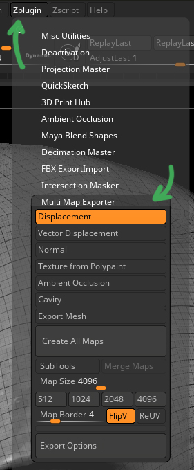
With the tool visible (you can also pin it to dock the tool), first enable Displacement and enable FilpV (as ZBrush has a tendency to flip things). Then click on Export Options to reveal more settings and click on File names. When the window pops up, click on the UV tile ID format until it switches to <UDIM>. This is to ensure our files are output using a UDIM naming convention.

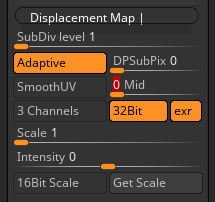
Displacement Map Settings
Next, click on the Displacement Map roll down and set the following:
- SubDiv level: 1 (or the level you would like to extract the map from)
- Adaptive: Enabled (creates a more accurate result but takes longer to calculate)
- DPSubDixPix: 0 (feel free to experiment with this for higher quality results)
- SmoothUV: Disabled (you may need to enable this. You will need to double check your subdivision settings in your renderer to align the settings)
- Mid: 0 (this will match the default Maya/Arnold setup. For some renderers/game engines, you will need to set this to 0.5)
- 3 Channels: Disabled (we only need to export the displacement map to one channel)
- 32bit: Enabled (for best results, we’ll be going with a 32bit floating point exr)
- exr: Enabled (you could write out a tif but I prefer to stick with exr)
- Scale: 1
- Intensity: 0
For more details on the settings, make sure to check out the official ZBrush docs here:
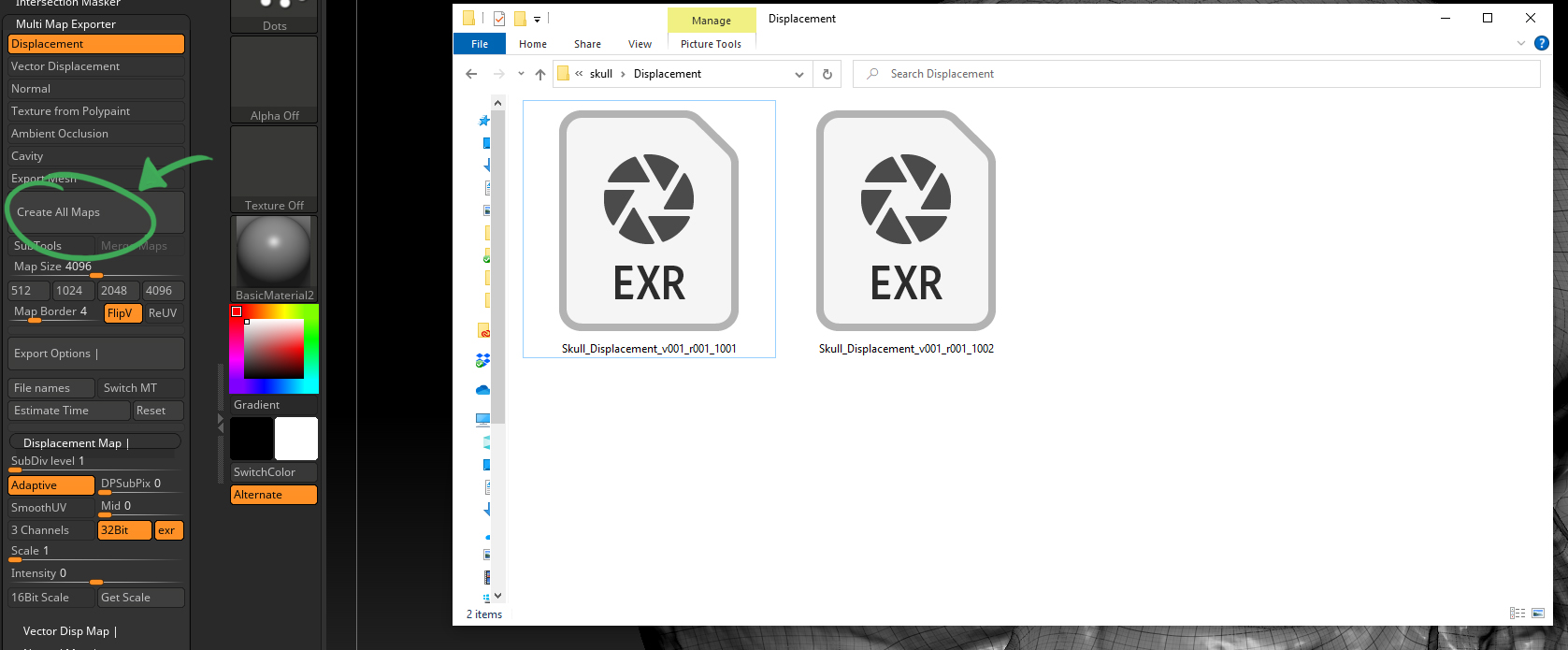
Exporting the 32bit Displacment Map
At this stage, we should be good to go. To export the displacement map, hit Create All Maps, and then give your map a name. Once you hit Save, the displacement maps should start to be generated, and you should end up with something like this on disk (I’ve renamed the files):
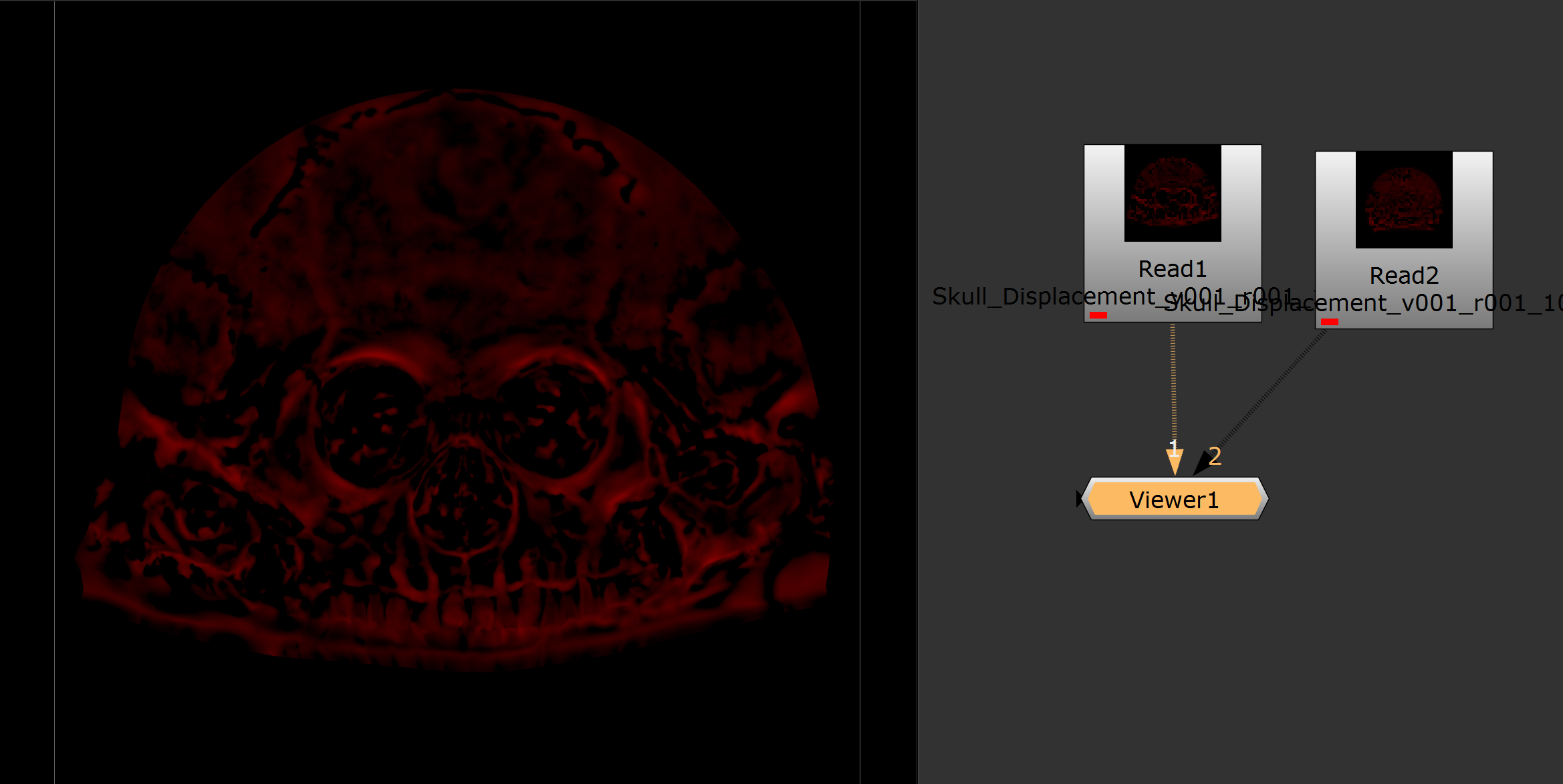
Reviewing your Displacement Map
If you load the images into Nuke or Photoshop, you should see something like this (where the displacement has been baked into the Red channel). If you mouse your mouse cursor over the image, you’ll see the numbers fluctuate to indicate how the points of the 3d model will be pushed and pulled.
Testing your Map in Maya/Arnold
I’ll be using Maya/Arnold to test the displacement map but you should be able to follow along with most renderers and applications.
Now that we have our displacement map, let’s check it works in Maya/Arnold. For this example, I have loaded the Lod1 skull model into the Maya Prop Look Dev and Lighting Turntable Project 1002, which is using an ACEScg profile.
I’ve then reframed the asset and tweaked the size and position of the grey/chrome balls (so they resemble large marbles). On the model, I have applied a Standard Surface material and set the Base Colour to 0.5 (mid grey) and the Specular Roughness to 0.350. One quick note, if you find your model looks faceted, run Mesh Display > Soften Edges over your model.
For more details on the Arnold Standard Surface Shader, check out the official docs here:

My first render out of the box (with no smoothing) looks like this:

To get the displacement going, we need to do 2 things.
- We need to apply the displacement texture to our shader
- We need to subdivide the model at render time so we have enough points for the texture map to push and pull
Subdividing the Model at Render Time
Let’s start with subdividing the model at render time.
In the Arnold RenderView, go Window > Toolbar Icons > Show Debug Shading icon. This will enable a drop-down that allows you to assess your render.
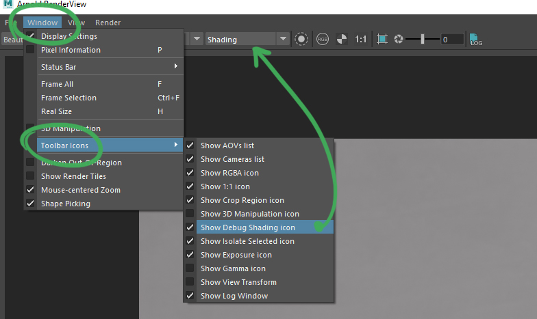
Switch this to Wireframe, hit render, and you should have something like this:
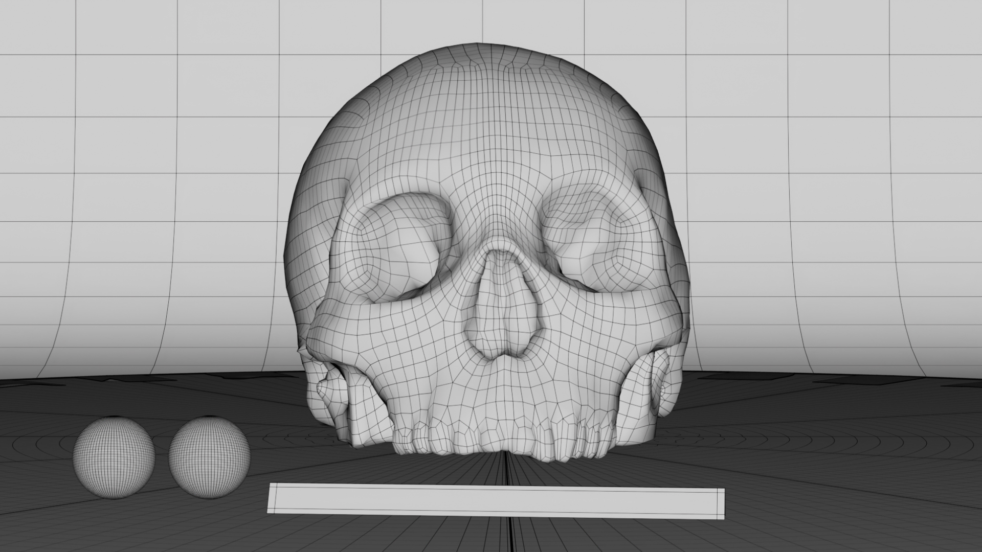
As you can see, we currently have no subdivision levels on our skull. To enable subdivision levels at render time, select the geometry and go to the Attribute Editor. Then go to the Shape node tab and open up the Arnold drop-down followed by Subdivision.
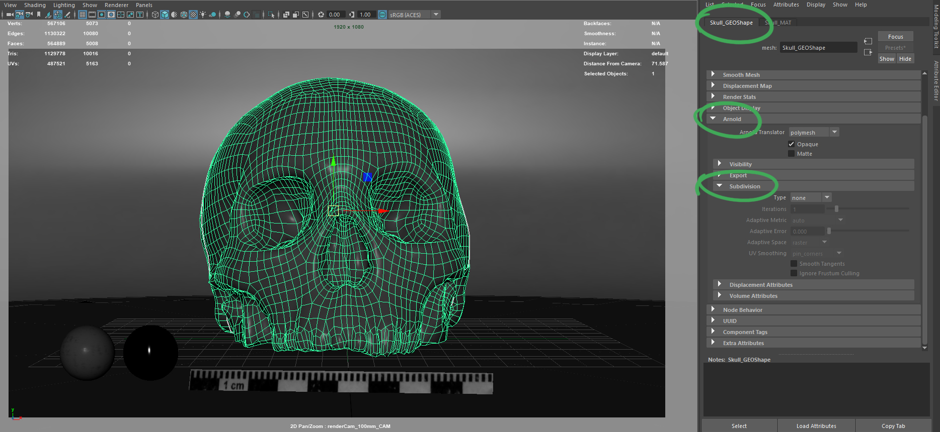
Next, enable Type: catclark and set the Iterations to match your highest subdivision level in ZBrush. In my case, this is 5. I tend to go between 5 and 6 levels of subdivision in Maya/Arnold. Any more than that and it can take a long time to render. If you need to pull out more detail, using a displacement map in combination with a normal map will probably do the trick. If you hit render again with increased subdivision Iterations, you should now see that your skull has been subdivided. Below you can see example renders at Iterations of 1, 2, 3, 4, 5 (which I’ll be sticking with) and 6.

Applying the Displacement Map to the Shader
In Maya, open up the Hypershade and graph your Skull_MAT, so you have access to the Shading Group (SG) node. We’ll be plugging the displacement file into this node.
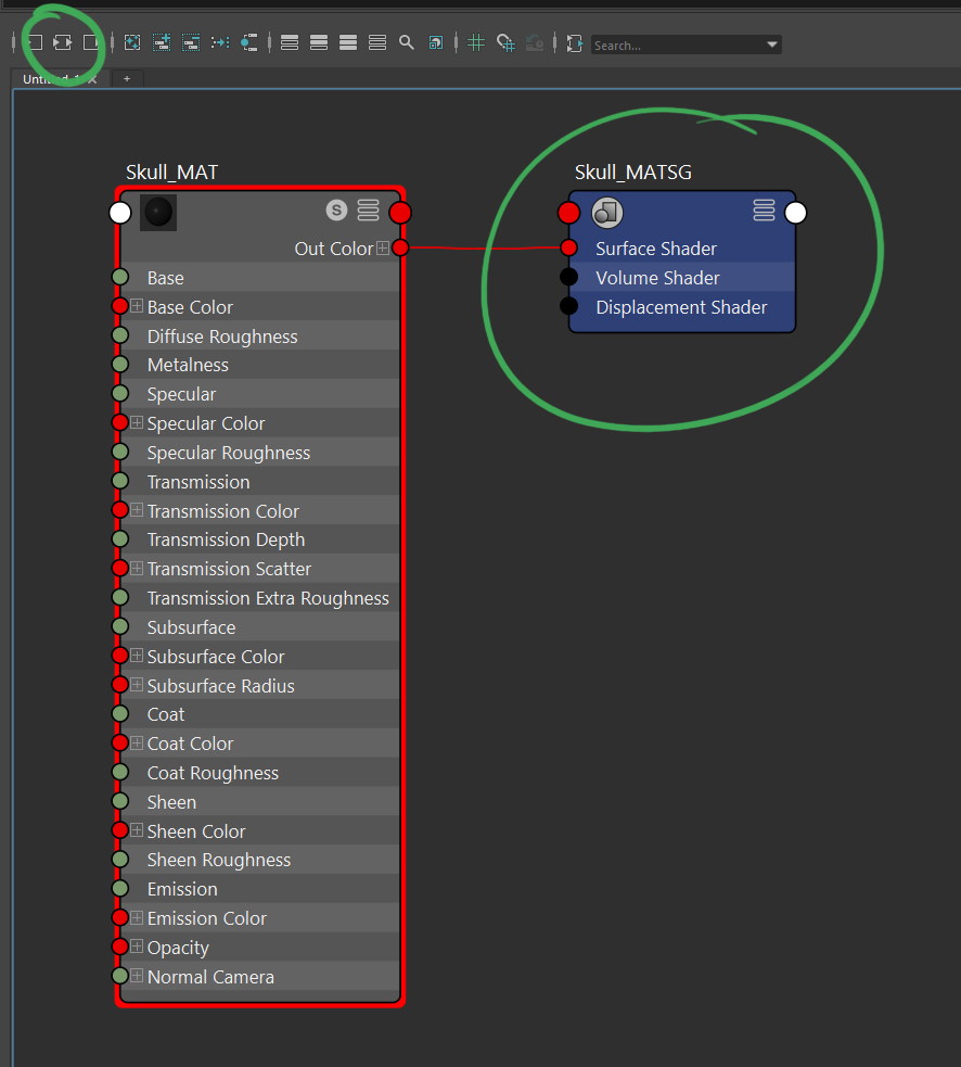
With the SG node selected, in the Attribute Editor, click on the checker icon and select File from the Create Render Node window.

Your shader graph should now look like what I have below with the displacementShader1 node plugged into the node and the file plugged into the Displacement parameter. Next, click on the file node or the input icon.

You should now be able to click on the folder icon and point to your displacement map. You will only need to select one of the maps, even if you have multiple UDIM files. Next, on the file node, set the following:
- UV Tiling Mode: UDIM (Mari) (this should find all the additional UDIM maps if they are named correctly)
- Color Space: Utility – RAW (this is so no tweak is applied to the image. We want them as they are)
- Alpha is Luminance: Enabled (this will use the luminance of the image as an alpha)

And with that – you should now be good to go. hit render and see what you get. Here is my render:
Troubleshooting
Here are some things to look out for if you are having issues with your displacement:
- Is your base mesh in Maya the same model as your lowest subdivision model in ZBrush? If not, the vertices may be out of alignment. This is because any sculpting you do in ZBrush on the base model (even when sculpting at a higher subdivision) will more than likely change the underlying geometry. So, either export out your lowest resolution model from ZBrush back into your application of choice or create a blendshape between them to align them. There are other things you could do but we’ll tackle that in a separate doc.
- Is your displacement looking funny? Check your UVs to make sure they are not flipped.
- Do you have displacement, but it looks strange? Check your mid values and make sure they match between applications. In Maya, you can check them under Displacement Attributes on the object shape node, or on the Displacement Shader node.

Links
- Setting up a PBR Metal/Roughness Shader – In this doc, we’ll cover how to set up your PBR Metal/Roughness shader.
Support CAVE Academy
Here at CAVE Academy the beauty of giving and sharing is very close to our hearts. With that spirit, we gladly provide Masterclasses, Dailies, the Wiki, and many high-quality assets free of charge. To enable the team to create and release more free content, you can support us here: Support CAVE Academy