
Search the wiki
Modelling a Classic Car in Maya

Resources
The following zip file contains a Maya project with scenes and reference images:
caveAcademy_modellingAClassicCarInMaya_resources
Introduction
This tutorial will run through modelling a classic car, namely a Sunbeam Rapier Mark IV, and the focus will be on using hard surface modelling techniques.
Throughout we’re going to stick to basic modelling theories such as modelling in quads and achieving evenly spaced faces, which then allow for sculpting in Mudbox or Zbrush if you need to. As we go there’ll also be an insistence on creating plenty of bevelled edges in order to stick closely to real world examples and avoid getting a flat CG representation of reality.

I’ll be using Maya, but it’ll be the techniques not the tools that will be the focus, and these techniques are easily transferable to other 3D software packages. I’m of the opinion that as a modeller it’s your experience, your perseverance and your eye which make the difference, not the tools you choose to use.
For my reference, I must give huge thanks to Graeme Jenner (www.classiccarportraits.co.uk) who kindly allowed me to use his beautiful portrait of the Rapier, which has been reproduced here. I also used an Oxford Diecast model to have physical reference as well as numerous images and videos I have found online to help me piece the model together. The more information I have, the less guess work I have to do when in Maya.

To explain briefly the process, I firstly drew over the reference to get a basic topology before hitting CG: it’s preparatory work which in general stands you in good stead. In this tutorial the draw-overs provided the image planes in Maya and they acted as a rough guide as I blocked out the model, but the further we progress, the more we have to rely on our wits and intuition to get a good edge flow. Then, just as you would a drawing or painting, I blocked out the major forms to provide a solid foundation before going anywhere near finer detail. The elements of the car were all modelled separately, as they would be in the real world, which makes it easier to rig for animation if needed. And finally the good news is that you only have to model half a car, as you can mirror it over.
Modelling is a bit like doing a puzzle, hopefully a fun puzzle…
Step 01: Bringing in the reference
Create a new scene and navigate to the ‘Front’ orthographic view. Reset the camera by going View>Default View in the Viewport panel menu. Now go View>Image Plane>Import Image and select ‘referenceFront_v1.tif’ when the Open screen pops up. Open up the Attribute Editor and check ‘Use Image Sequence’. Take the ‘Alpha Gain’ down to 0.4 also. Move into the ‘Side’ orthographic view and set it to Default View. Import ‘referenceSide_v1.tif’ and give it the same settings as the front image. Do the same for the top view, loading in ‘referenceTop_v1.tif’ as the reference. Once all three reference planes are in, check that they line up in the ‘Perspective’ view. Using the ‘Center’ attributes for each image plane, push them all along their corresponding axis so we have space to model in the centre of the world space.

Step 02: Using back and front references together
The reference has been set up in a manner that allows us to use the timeline to switch between the original image, the topology draw-over and a coloured draw-over indicating the separate pieces. Set your animation range slider to go from frames 1 to 6. Now if you scrub between frames 1 and 3, you will view the front of the car and frames 4 to 6 will reveal the back. To rotate our model to match this, create an empty group node by hitting Ctrl/Cmd+G. Rename the group ‘car_grp’ and set a key at frame 1 and frame 3. Now scrub to frame 4 and put a value of 180 in its rotate Y channel and set another key. Every object we create (excluding lights) will be placed in this group so it follows our reference correctly.

Step 03: Blocking out the base
Go to Create>Polygons Primitives and create a ‘Plane’. Under its Inputs in the Channel Box, take down its Subdivision Width and Height to1. Now position and orient it against the side of the car. Go into Edge mode and use the Extrude tool found under Edit Mesh to begin blocking out the main base. Use large shapes to fill out the silhouette as much as possible with as few polys as you can. I’m a big fan of Edge Modelling but there’s no reason why you couldn’t use a box modelling technique to rough out the form if preffered.

Step 04: Continue the blocking
Continue to block out the base in the front and top view and also importantly, check your model constantly in the Perspective View. At this stage, you’ll probably find that the reference does not line up 100%. In a situation like this, I like to decide on one key image, in which I will line everything up, and the remainder of the images will act as more of a loose guide. As well as extruding edges I like to use the ‘Insert Edge Loop Tool’ found in the ‘Edit Mesh’ menu tab. As long as the model is in quads, this will cut through cleanly. As you add more detail, make sure to try to keep the faces of a similar size to each other.

Step 05: Using Duplicate Special
To reduce our workload and get a better feel of a complete car, let’s mirror the model over. First, turn on the translate tool and hit the ‘Insert’ key (or hold the D key) on your keyboard to be able to edit the position of the pivot. Now hold the X key on the keyboard and grid snap the pivot to the X-plane in the front view. Hit ‘Insert’ to come out of edit pivot mode. Next, go to Edit>Duplicate Special (Options). Set the Geometry type to ‘Instance’. Scale in X to -1 and hit Duplicate Special. As we go through the modelling of the car, we will be doing this many times.

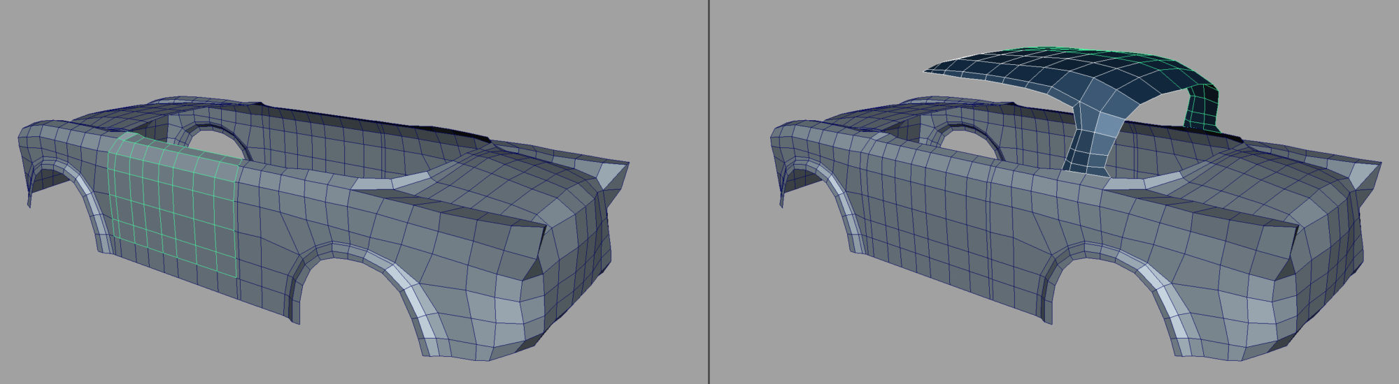
Step 06: Door and Roof
Start blocking in the door and the roof panels. Again, I’ve begun each piece with a single plane and extruded or added edge loops for more detail. To get the flow between the separate elements working well, I’m holding down the V key on the keyboard to point snap the border vertices of the door and the roof onto the main base. Once I’m happy with the initial blocking, I will use the Duplicate Special to mirror the geometry over.
Step 07: Adding the window rims
To get the window rims in place, I draw a curve using Create>CV Curve Tool. Holding down the V key on the keyboard, I point snap each CV to a vertex of the window and the base of the car. Next, create a polygon cube and shrink it down to be similar to the size of the rim. Now place it at the beginning of the curve you have drawn and go into Face mode. Select the face that is adjacent to the curve and shift-select the curve also. Go to Edit Mesh>Extrude and increase the divisions to around 20 and the extrusion should grow along the curve. Continue to create the front window rim and the side window rim using the same technique.

Step 08: Adding some windows
Once the window rims are in, create some windows using polygonal planes as well as putting in the front window frame. As you move around the model, continue to check the car from all angles and smooth out the flow of the edges and keep the model as clean as can be. At this stage, I would select all the geometry and go Edit>Delete By Type>History. Deleting the history frequently will keep our scene file nice and light. You can also delete the curves used to create our window rims as the ‘link-up’ between them and the polygon faces have now been broken.

Step 09: Bonnets and Bumpers
To create the bonnet, I selected a range of faces from the main base of the car where the bonnet should be situated. I then went Edit Mesh>Duplicate Faces to make a copy of those faces. This will allow me to get the flow between the main base and the bonnet working well. I added some tight edges around the border of this new piece to add some solidity and depth to the bonnet. Later on, I’ll re-use this for the boot panel of the car. For the bumper, I began with a default cube and by inserting edge loops I was able to match it closely to the reference image. The bumper can also be duplicated and used at the rear of the car.

Step 10: Lights and Grills
At this stage, I’m happy with the initial blockout, although much tweaking will continue, and I’ll begin to add some of the key details that make this car distinct. For the headlight, I began by selecting some faces at the front and extruding them into the car. After some point pushing to get this region as round as can be, I placed a semi-sphere into the cavity. Further basic polygon cubes were shaped to form the Rapier’s ‘eyelids’ and some tight rims around the headlight to sit it in more realistically. The grill and indicator lights were also pushed from simple shapes such as cylinders, cubes and spheres that were refined with adding edge loops or extrusions. To get them to sit flush against the front of the car, I used a Lattice deformer from the Animation panel. Using the lattice points, you can quickly and effectively reshape the mesh.

Step 11: Lights and Grills
Quick note – for the hubcaps, you’ll see that all the points come together at a pole. Although this was fine for this asset, we recommend trying to have as few edges as possible coming together at poles. This will reduce rendering artefacts. Fore more information, check out this doc:
The hubcaps, although they may look pretty complex, were very quick to create. First I created a cylinder and deleted all the faces other than the top. I then added extra edge loops to help define the areas that will need pulling out or pushing back. These sections were then extruded out and the entire model then smoothed using the Mesh>Smooth tool. I then selected a row of faces, disabled ‘Keep Faces Together’ under Edit Mesh and performed another extrude. This time, I scaled in the faces in X and Y and then extruded the new faces inwards. Finally, to get rid of the roundness of the detailed areas, I added to two edge loops around the recessed areas. The tyre was created from a Torus shape and under its Inputs, I was able to use the Section Radius to help block out its initial shape. Adding extra edge loops then helped to reduce its softness.

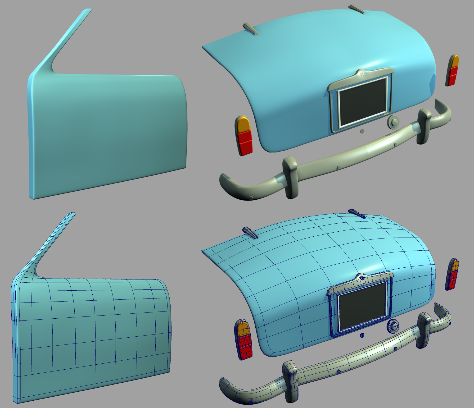
Step 12: Creating the wings
To create the distinct wings of the Rapier, extra edge loops were needed. As I did not want all the edge loops to cut through the side of the model, I used the Split Poly tool. Extruding out from the back of the wings also allowed me a base to sit the rear lights onto and adding a tight edge in the region helped to hold their unique shape when smoothed. I also hollowed out the boot as it would be in a real car. This allowed me to sit the boot door nicely into the cavity and create a more believable tight shadow in between the surfaces.

Step 13: Beveling the base and the top
So now that we have our main forms in place, we need to start adding some solidity to them and give them some thickness. To do this we need to bevel the edges of the components. I began by adding tight loops around the main base and the window frame. Then I extruded out the outer edges and pulled them in. The metal rims around the window frames also needed a bevel to them. Leaving them without a bevel either made them too flat in unsmoothed mode or too rubbery in smoothed mode. For the roof, I also selected all the faces and did a large extrude inwards. This allowed me to use the depth of the roof to rest the side windows against.

Step 14: Beveling the door and more.
I continued to bevel the door and the bonnet of the car. The lights at the rear and the majority of the metal work around the car also had their edges bevelled. This will help the light hit the edges and create nice highlights adding to the overall believability of the model.
Step 15: Finalising the model
To add some richness to the model, it’s important to add the finer details, such as the strips running along the model and the logo on the door. I have also used some simple geometry for the side mirrors and modelled the window wipers and the door handle. Once we are happy and tweaked to our hearts’ content, we can delete the duplicated side. We can again use the Duplicate special to create the missing half, only this time, set the Geometry Type to ‘Copy’ in the Options box, or you can use the Mirror Geometry tool found under Mesh. If you are using the Duplicate Special tool, you will need to combine the individual halves by going Mesh>Combine and then merge the center vertices that are sitting on top of each other. Happy modelling.
Tip 01: Lights, camera, reaction!
It’s really worth setting up some lights in the scene as you go so that you can see how the surfaces of the model and components react to light. I throw in a few spotlights, which stay in place and are used as fill lights, and one directional light, which will be my key light, and will have shadows turned on. Every now and then as I work, I change the direction of the key light to get a feel for what’s working and what isn’t.
Another tip is to use Viewpoint 2.0 with Ambient Inclusion turned on and off periodically. This gives a good indication of how well objects are juxtaposing by enabling you to see the “nitty gritty” shadows.

Tip 02: Can’t see the woods for the CG trees.
I find that the number of parts created in this kind of modelling process can make your workflow feel awkward as they simply get in the way. Using Isolate Select enables you to hone in on the areas required. You can find this setting under ‘Show’ in the Viewport panel menu. Additionally, using Layers lets you show and hide objects to achieve the same effect.